Do you always need ODT when working with DDR memory?
- Dec 11, 2023
- 2 min read
Updated: Jan 18, 2024
Introduction - General information about DDR memories
DDR memory is capable of transferring data at very high speeds. For example, DDR3 can transfer up to 1.6 GT/s, with a rise time of 350 ps. These speeds, made possible by the short rise times, among other things, manifest themselves in an increasing bandwidth. For a rise time of 350 ps, we will get a bandwidth of 1 GHz.
The meaning of these wide bandwidths is the need to address the signal integrity of the signals, among other things, to ensure appropriate terminations regarding value, topology, and location on the PCB.
What is ODT?
ODT stands for On-Die Termination. DDR memory manufacturers and processors that interface with memory integrate terminations within the die to save PCB space and reduce BOM and assembly costs. Different termination values can be selected according to the specifications. ODT is a feature supported in DDR2 and DDR3, while DDR1 does not have ODT terminations. Enabling ODT and selecting the appropriate termination value depends on both the software and the ODT pin on DDR2 and DDR3 memories and the processors, FPGAs, DSP components, etc., that control memory components.
It is essential to emphasize that ODT if it exists, is relevant only for DATA, DATA MASK, and DATA STROBE lines. ODT does not support control, clock, and address lines.
What if the controller you are working with does not support ODT?
Many processors support ODT, but some not, such as the AT91SAMG15 from ATMEL. This component has a DDR2 interface but does not support ODT. Lack of ODT support will be more critical in systems intended for the consumer market, where the cost of each component and assembly is significant. If there is no suitable solution, we must use external terminations.
The solution:
If the distance between the controller and the DDR memory is short enough, it may be possible to work without ODT terminations and without the addition of external terminations. How short? So short that the total routed line length is no more than 1 inch.
It is important to remember that even if the line is short, if the output stage drive strength is not selected appropriately, we will still encounter problems of high-amplitude reflections that will cause overshoot, undershoot, ringing, and, in fact, will result in signal integrity degradation.
Example based on SI simulations:
In the following example, a single DDR2 component is used connected to AT91SAMG15. The safest way to get a working card will be to run simulations before manufacturing the PCB.
The following illustrations show simulations performed using the Hyperlynx 8.1.1 of Mentor Graphics.
Since the DATA signals are bidirectional, it is important to remember that a simulation must also be performed for two cases:
DDR drives the controller.
The Controller drives the DDR because these are bidirectional DATA lines.

Figure 1 – Topology
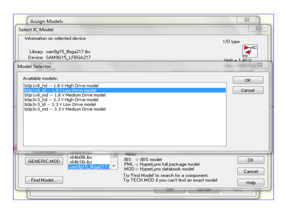
Figure 2 - Shows the correct choice of the model in building the topology
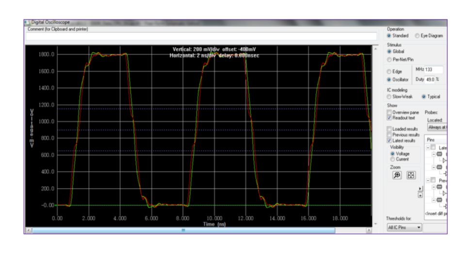
Figure 3 - Shows the correct choice of the model in building the topology
Conclusions:
Point-to-point DDR signals can be designed and routed without necessarily using external terminations or On-Die-Termination.
This conclusion is based on various parameters, such as:
Signal trace length on the PCB.
DDR interface bit rate.
DDR and Controller driving strength.


